FPV Propeller Selection, ESC vs 4-in-1 ESC Stack: Architecture Differences and Which Setup Suits Each Build Style
FPV propeller selection affects the electrical load placed on a drone’s motors and electronic speed controllers. However, propeller choice is only one part of the power system. Builders must also decide how the four motor-control channels will be packaged: as four individual ESCs or as one integrated 4-in-1 ESC board.
An FPV quadcopter needs four electronic speed controller channels because each brushless motor must be controlled independently.
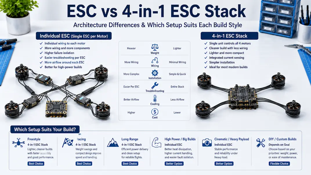
An individual ESC setup uses one separate controller for each motor, commonly mounted on the corresponding frame arm. A 4-in-1 ESC places all four motor-control channels on one PCB, normally installed below the flight controller in the center of the frame.
Both architectures can operate the same four-motor aircraft when their electrical ratings are appropriate. Their main differences involve:
- wiring complexity;
- soldering requirements;
- component placement;
- total installed weight;
- heat distribution;
- crash exposure;
- repair cost.
Neither architecture automatically produces more thrust, smoother flight, or better throttle response. Those outcomes depend on the complete motor, propeller, battery, ESC, and flight-controller combination.
What Is an Individual ESC Setup?
An individual ESC layout uses four physically separate electronic speed controllers. Each ESC receives a motor command from the flight controller and controls the three electrical phases connected to one brushless motor.
A typical installation includes:
- one ESC for each motor;
- separate power and ground connections;
- one motor-signal path per ESC;
- three phase-wire connections per motor;
- separate insulation and mounting for each controller.
The four controllers are physically independent, but they normally share the same battery, ground reference, power-distribution system, and flight controller.
Individual ESCs are often mounted on the frame arms. This keeps each controller close to its motor and reduces the required motor-wire length.
They can also be positioned elsewhere when a larger or custom frame provides protected distributed mounting locations.
What Is a 4-in-1 ESC?
A 4-in-1 ESC combines four independent motor-control channels on one central circuit board.
Instead of distributing battery power to four separate controllers, the main battery lead connects to one board. That board contains four power stages and four groups of motor-output pads.
A typical central electronics stack includes:
- one 4-in-1 ESC board;
- one separate flight controller;
- mounting screws and spacers;
- vibration-isolating grommets where required;
- a short inter-board harness or soldered connection.
The flight controller and 4-in-1 ESC remain separate devices.
The flight controller processes sensor information and generates motor commands. The ESC receives those commands and controls electrical output to the motors.
The term ESC stack describes the physical arrangement of the boards. It does not mean the flight controller and ESC perform the same function.
FPV ESC vs 4-in-1 ESC: What Is the Main Difference?
The main difference is how the four motor-control channels are packaged and positioned.
With individual ESCs, each channel has its own board. With a 4-in-1 ESC, the channels share one PCB and one central mounting location.
| Design factor | Individual ESCs | 4-in-1 ESC |
|---|---|---|
| Number of boards | Four | One |
| Typical position | Distributed across the frame | Central electronics stack |
| Battery wiring | Routed to four controllers | Connected to one board |
| Motor signals | Individually routed | Usually carried by one harness |
| Heat location | Distributed | Concentrated centrally |
| Failed-channel repair | Replace one ESC | Usually replace the complete board |
| Arm space | Requires mounting room | Keeps the arms clear |
| Central space | Uses less stack space | Uses central stack space |
| Installed weight | Usually higher | Usually lower |
| Build consistency | More routing variation | Easier to standardize |
These are architectural differences. They should not be interpreted as proof that one format has inherently better electrical performance.
1. Wiring Complexity
Wiring is one of the clearest differences between individual ESCs and a 4-in-1 board.
Individual ESC wiring
Each separate ESC needs:
- battery power;
- ground;
- one motor-control signal;
- three motor-phase connections;
- optional signal ground or telemetry wiring.
The builder must distribute these connections toward four separate locations.
This usually produces:
- greater total wire length;
- more individual solder joints;
- more insulation points;
- more strain-relief locations;
- additional wiring along the frame arms.
Each wire must be protected from sharp carbon edges, damaged propellers, moving components, and repeated crash movement.
An individual layout can still be clean and reliable, but it requires careful wire measurement and routing.
4-in-1 ESC wiring
A 4-in-1 ESC centralizes most power and control connections.
The battery lead connects to one board. Motor wires from all four arms return to grouped pads in the central electronics bay.
A short harness or grouped solder connections normally carry the four motor-control signals from the flight controller.
This generally provides:
- fewer distributed power wires;
- shorter signal paths;
- fewer separate mounting points;
- a cleaner central installation;
- easier replication across identical builds.
A centralized layout does not eliminate connection errors. Battery polarity, motor-pad assignment, connector orientation, and harness pin order must still be verified before power is applied.
Two connectors can have the same shape while using different pin arrangements.
2. Soldering and Assembly Work
Four separate controllers normally require more assembly work than one integrated board.
The following tasks must be repeated for each individual ESC:
- choosing a mounting position;
- measuring and cutting wires;
- soldering power and ground;
- attaching the motor signal;
- connecting the three motor phases;
- insulating the board;
- securing the wiring.
A 4-in-1 ESC concentrates most soldering in one location. Motor wires must still reach the center, but power distribution and controller mounting are not repeated four times.
This makes a central board easier to standardize across several aircraft.
Individual ESCs can still be practical when the ability to replace one controller is more important than reducing initial assembly time.
3. Electronics Placement
The frame determines whether centralized or distributed ESC placement is practical.
Central placement
Most modern racing and freestyle frames provide a standard mounting pattern in the main body.
A 4-in-1 ESC uses this area efficiently when the frame has:
- a compatible mounting pattern;
- enough vertical stack clearance;
- protected center plates;
- space for motor-wire routing;
- airflow around the electronics.
The disadvantage is component concentration.
The ESC, flight controller, capacitor leads, receiver wiring, video hardware, and other connections may compete for limited central space.
Distributed placement
Individual ESCs move motor-control hardware away from the main electronics stack.
This can provide:
- additional central space;
- shorter ESC-to-motor wiring;
- flexible placement in custom frames;
- direct access to each motor circuit.
The arms must be wide enough to support and protect the controllers.
Narrow arms may leave the ESCs exposed to impact or place them close to the propeller path.
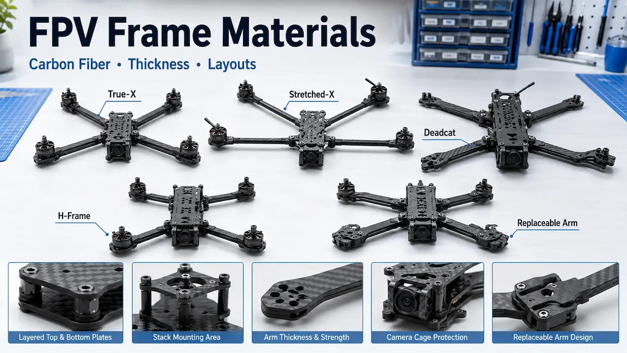
The previous guide to carbon fiber layouts covers frame construction in more detail. For this comparison, the relevant issue is whether the frame provides suitable mounting space for the selected ESC architecture.
4. Total Installed Weight
A 4-in-1 ESC usually creates a lighter complete installation in a conventional quadcopter.
One integrated board can share:
- one PCB;
- one battery-input area;
- one mounting position;
- common filtering components;
- one flight-controller interface.
An individual arrangement requires four PCBs plus additional power wiring, signal wiring, insulation, solder, and mounting material.
The comparison should include the entire installed system. Comparing the advertised weight of one individual ESC with one 4-in-1 board gives an inaccurate result because four individual units are required.
When lower weight matters
Reducing installed weight is particularly important for racing builds.
Racing pilots and builders commonly minimize:
- unnecessary wiring;
- separate boards;
- protective material;
- mounting hardware;
- excess solder.
On larger or less weight-sensitive aircraft, several additional grams may matter less than repairability or central-space availability.
5. Heat Distribution
Both architectures generate heat, but they place it in different areas.
Individual ESC heat
Four individual controllers distribute their heat across four physical locations.
This may:
- reduce heat concentration in the center;
- separate the four power stages;
- expose each controller to direct airflow;
- make one unusually hot controller easier to identify.
Distributed placement does not guarantee effective cooling.
Heat-shrink, tape, guards, wires, frame geometry, and low-speed operation can restrict airflow around an arm-mounted ESC.
4-in-1 ESC heat
A 4-in-1 board places four power stages on one PCB. The resulting heat is concentrated inside the central electronics bay.
Operating temperature depends on:
- component efficiency;
- PCB construction;
- current load;
- stack spacing;
- surrounding hardware;
- available airflow;
- ambient temperature.
A tightly compressed stack may retain more heat than a distributed installation.
A correctly rated and adequately ventilated 4-in-1 board can still operate reliably. The actual comparison is distributed heat versus centralized heat, not cool versus hot.
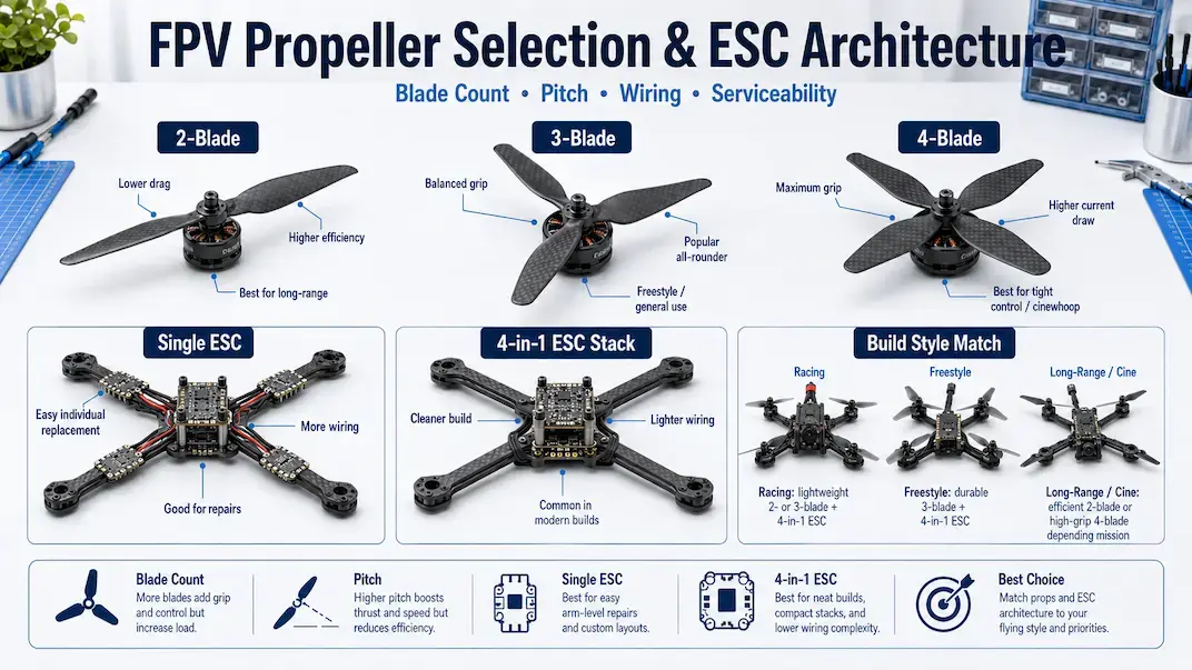
How FPV Propeller Selection Affects ESC Load
FPV propeller selection influences how much mechanical resistance the motor must overcome. Changing propeller diameter, pitch, blade count, or mass can change motor current demand.
That does not determine whether an individual or integrated ESC architecture must be used. It determines the electrical capacity the selected controllers need to provide.
For either layout, the ESC must support the load produced by the complete combination of:
- motor specification;
- battery voltage;
- propeller configuration;
- aircraft weight;
- flying conditions.
A more demanding motor-and-propeller combination can increase current and heat in either individual ESCs or a 4-in-1 board.
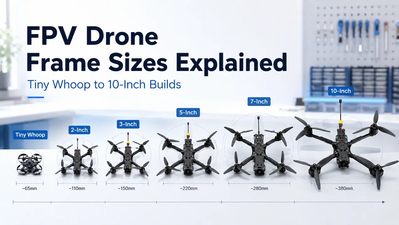
This article does not own detailed propeller sizing, pitch selection, blade-count comparison, or motor-KV matching. Those subjects require their own dedicated propulsion articles.
The relevant point here is simple: ESC architecture controls how the channels are packaged, while the motor and propeller combination controls much of the load applied to those channels.
6. Physical Exposure
ESC position changes the type of physical damage the controller may experience.
Individual ESC exposure
Arm-mounted controllers are closer to common impact areas.
They may be exposed to:
- broken propellers;
- direct ground contact;
- bent or fractured arms;
- pulled motor wires;
- damaged insulation;
- sharp carbon edges.
Protective covers and wire restraint can reduce these risks, but they add material and assembly work.
4-in-1 ESC protection
A central board is usually protected by the main frame plates.
This reduces direct exposure to arm impacts and broken propellers.
A central board can still be damaged by:
- frame compression;
- loose conductive hardware;
- displaced battery wiring;
- stack screws contacting components;
- debris inside the frame;
- electrical faults.
Central placement improves physical protection but does not make the ESC immune to damage.
7. Repair and Replacement Cost
Replacement scope is one of the most important differences between the two architectures.
Replacing an individual ESC
When one separate ESC fails, the builder can normally replace only that unit.
The other three controllers can remain installed when they are undamaged and working correctly.
This provides:
- lower replacement cost per failed channel;
- less functioning hardware discarded;
- smaller spare-part requirements;
- independent access to each motor circuit.
The repair still requires the failed controller to be removed, rewired, insulated, and tested.
An individual ESC is not necessarily faster to replace, but the replacement is limited to one motor channel.
Replacing a 4-in-1 ESC
A 4-in-1 board contains four distinct channels. One channel can fail while the remaining three continue to function.
However, the channels share one PCB. In most cases, one unusable channel requires replacing the complete board.
Replacement may require:
- opening the central stack;
- disconnecting all four motors;
- removing the battery lead;
- transferring supporting wiring;
- checking the signal harness;
- rebuilding and testing the stack.
Specialized board-level repair may be possible, but it is not a practical standard repair for most FPV owners.
The disadvantage is not that all four channels always fail together. The disadvantage is that one failed channel can make the complete integrated board unsuitable for flight.
Spare-Part Strategy
Each architecture supports a different spare-parts approach.
Individual ESC spares
A builder can keep one or two matching controllers available instead of storing a complete four-channel board.
This approach is useful when:
- single-channel repair cost matters;
- parts cannot be obtained quickly;
- several aircraft use the same controller;
- the build allows accessible module replacement.
A spare controller must still support the required battery voltage, signal protocol, current load, and motor configuration.
4-in-1 ESC spares
A builder using integrated boards may keep one complete replacement ESC or one matched FC-and-ESC stack.
The spare costs more, but it can simplify maintenance when several aircraft use identical:
- mounting patterns;
- connectors;
- harness pinouts;
- motor-wire lengths;
- board orientations.
Standardization can make complete-board replacement predictable, even though it costs more than replacing one individual ESC.
Which Setup Suits Racing Builds?
A 4-in-1 ESC is generally the more practical architecture for a modern racing quad.
Racing builds commonly prioritize:
- low total weight;
- compact electronics;
- narrow frame arms;
- limited wiring;
- consistent assembly;
- protected central hardware.
An integrated board supports those priorities and leaves the arms clear.
The main disadvantage appears after a channel failure, when the complete board normally needs to be replaced.
Individual controllers remain possible on frames designed around distributed electronics, but they are less common in compact modern racing layouts.
Which Setup Suits Freestyle Builds?
Most conventional freestyle quads also use a 4-in-1 ESC.
The integrated layout provides:
- a protected central installation;
- fewer arm-mounted components;
- simplified power distribution;
- compatibility with common frame designs;
- lower installed weight.
Individual controllers may appeal to builders who prioritize replacing only one failed channel.
That modularity creates a tradeoff. Arm-mounted controllers are positioned closer to crashes, damaged propellers, and broken frame sections.
For most standard freestyle frames, an integrated board is the practical default. Individual ESCs remain valid when the frame and maintenance strategy are designed around them.
Which Setup Suits Larger or Custom Builds?
Individual ESCs can be useful on larger or custom aircraft when protected distributed mounting positions are available.
Reasons may include:
- preserving central electronics space;
- separating heat sources;
- replacing one channel independently;
- accommodating a nonstandard frame;
- using controllers that do not fit a common stack pattern.
A larger aircraft does not automatically require individual controllers.
A suitable 4-in-1 board can still be used when its voltage support, current capability, thermal design, dimensions, and interface match the aircraft.
The architecture should follow the physical and maintenance requirements of the build rather than frame size alone.
How Does the Flight Controller Connect to the ESC?
The flight controller sends an independent command to each motor-control channel.
With separate ESCs, these commands usually travel through individually routed signal wires.
With a 4-in-1 board, the four commands commonly travel through one short harness or grouped solder connections.
Depending on the hardware, the interface may also carry:
- ground;
- battery-voltage sensing;
- current-sensor output;
- ESC telemetry.
The exact pin arrangement depends on the selected boards.
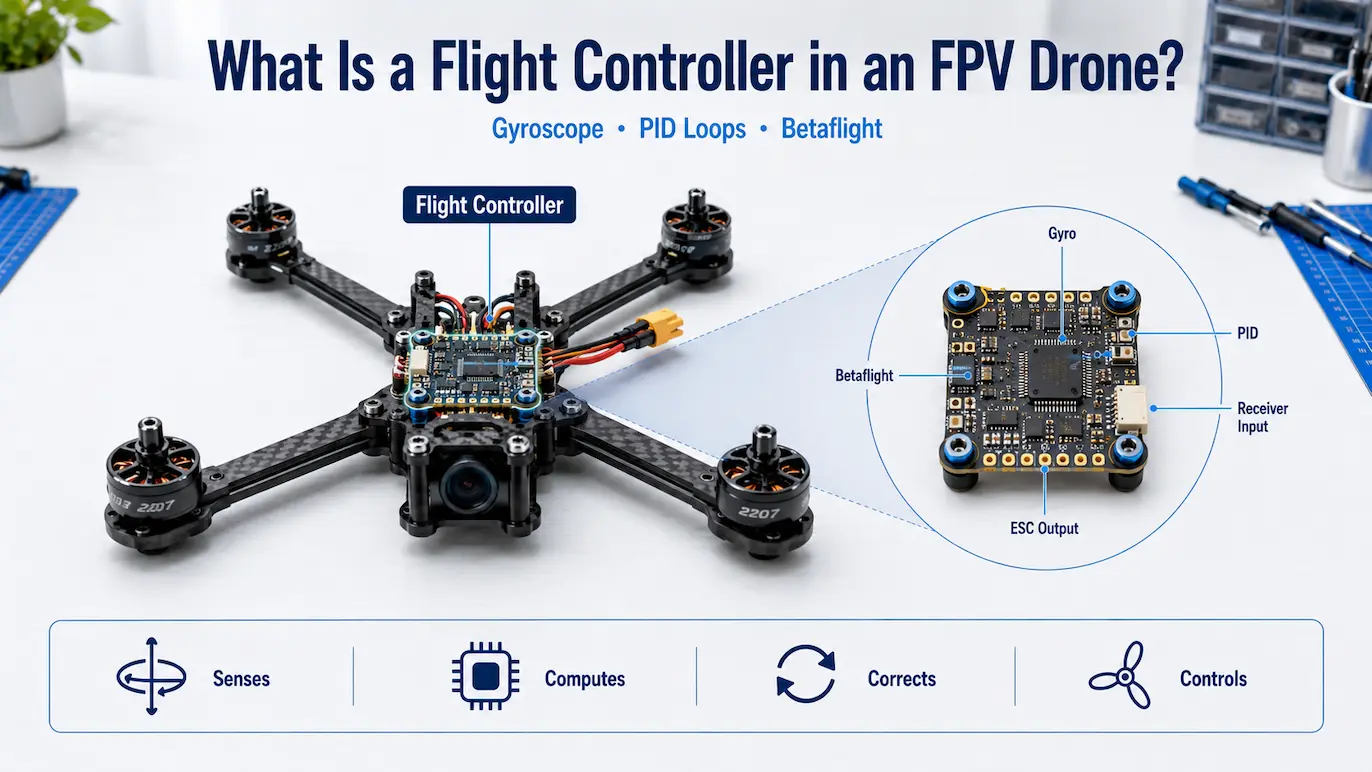
The upcoming guide to the FPV flight controller will explain gyro processing, PID correction, and Betaflight operation. Those functions belong to the flight controller rather than the ESC.
The official Betaflight documentation provides additional technical information about supported flight-controller and motor-output features. The ArduPilot motor documentation also provides an external reference for ESC and motor connections.
Electrical Compatibility Requirements
Choosing between individual ESCs and a 4-in-1 board does not replace electrical compatibility checks.
The selected hardware must support:
- battery voltage;
- expected continuous current;
- short-duration current peaks;
- motor-control protocol;
- mounting dimensions;
- available cooling;
- flight-controller interface.
The motor, battery, and propeller combination must remain within the realistic operating range of the ESC.
Advertised current ratings should be evaluated alongside test conditions, airflow, input voltage, and duration. A short burst rating is not the same as a sustainable continuous-current rating.
Individual ESC vs 4-in-1 ESC Comparison
| Selection factor | Individual ESCs | 4-in-1 ESC |
|---|---|---|
| Architecture | Four separate boards | Four channels on one PCB |
| Typical mounting | Distributed across the frame | Central stack |
| Wiring complexity | Higher | Lower |
| Soldering work | More repeated connections | More centralized |
| Installed weight | Usually higher | Usually lower |
| Heat placement | Distributed | Centralized |
| Central-space use | Lower | Higher |
| Arm-space use | Higher | Lower |
| Direct impact exposure | Usually higher | Usually lower |
| Failed-channel replacement | Replace one controller | Usually replace the entire board |
| Spare cost per repair | Usually lower | Usually higher |
| Assembly consistency | More variable | Easier to standardize |
| Racing use | Less common | Very common |
| Freestyle use | Less common | Very common |
| Custom-layout flexibility | Higher | Depends on mounting compatibility |
When Should You Choose Individual ESCs?
Choose individual controllers when the build prioritizes:
- independent channel replacement;
- distributed electronics;
- additional central space;
- custom frame compatibility;
- modular spare planning;
- protected arm-mounting positions.
This architecture makes the most sense when serviceability and placement flexibility matter more than minimum wiring and weight.
When Should You Choose a 4-in-1 ESC?
Choose an integrated board when the build prioritizes:
- compact construction;
- lower installed weight;
- fewer distributed wires;
- faster assembly;
- clear frame arms;
- standardized mounting.
A 4-in-1 board is generally the more practical architecture for contemporary racing and freestyle quads.
It must still match the battery voltage, expected current load, mounting pattern, cooling conditions, and flight-controller interface.
Builders comparing integrated hardware can review the flight controller ESC category. Component selection should be based on the electrical requirements of the aircraft rather than packaging alone.
Common Selection Mistakes
Treating the ESC and Flight Controller as One Device
A normal stack contains two separate boards. The flight controller generates motor commands, while the ESC controls electrical output to the motors.
Assuming Matching Connectors Have Matching Pinouts
Connector shape does not guarantee electrical compatibility. Check the pin arrangement for both boards before connecting them.
Comparing Bare Board Weight
Complete installed weight includes all wiring, insulation, solder, guards, connectors, and mounting material.
Assuming Individual ESCs Always Run Cooler
Physical separation can distribute heat, but actual temperature depends on load, airflow, insulation, and mounting position.
Assuming All Four Integrated Channels Failed
One 4-in-1 ESC channel may fail independently. The entire board is replaced because the channels share one PCB.
Ignoring Arm Exposure
Individual replacement is useful, but arm-mounted electronics sit closer to propeller strikes, frame damage, and ground impacts.
Choosing an Integrated Board Only for Cleaner Wiring
Simplified wiring does not replace electrical compatibility. Voltage, load, cooling, mounting, and connector requirements still apply.
Final Verdict
For most contemporary racing and freestyle FPV quads, a 4-in-1 ESC provides the more efficient architecture. It reduces distributed wiring, lowers installed weight, clears the frame arms, and supports a compact central electronics stack.
Individual ESCs remain useful when modular repair, distributed placement, central-space availability, or custom frame architecture matters more than minimum weight.
The decision can be summarized as follows:
- choose individual ESCs when replacing one motor-control channel independently is the priority;
- choose a 4-in-1 ESC when compact packaging, lower weight, and simpler assembly are the priorities.
FPV propeller selection still matters because propeller load affects motor current and ESC demand. However, it does not independently determine whether the controllers should be separate or integrated.
Neither ESC architecture automatically provides better motor performance. The real differences are wiring, placement, weight, heat distribution, physical exposure, replacement scope, and repair cost.
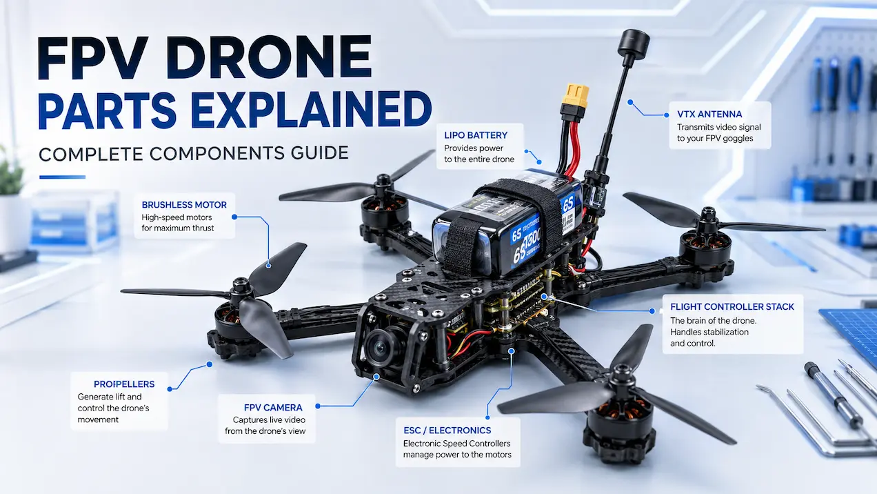
The broader FPV parts guide shows where the ESC fits within the complete aircraft. Additional FPV technical guides cover connected components without repeating this architecture comparison.