FPV Flight Controller Explained: Gyroscope, PID Loops, and Betaflight
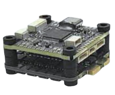
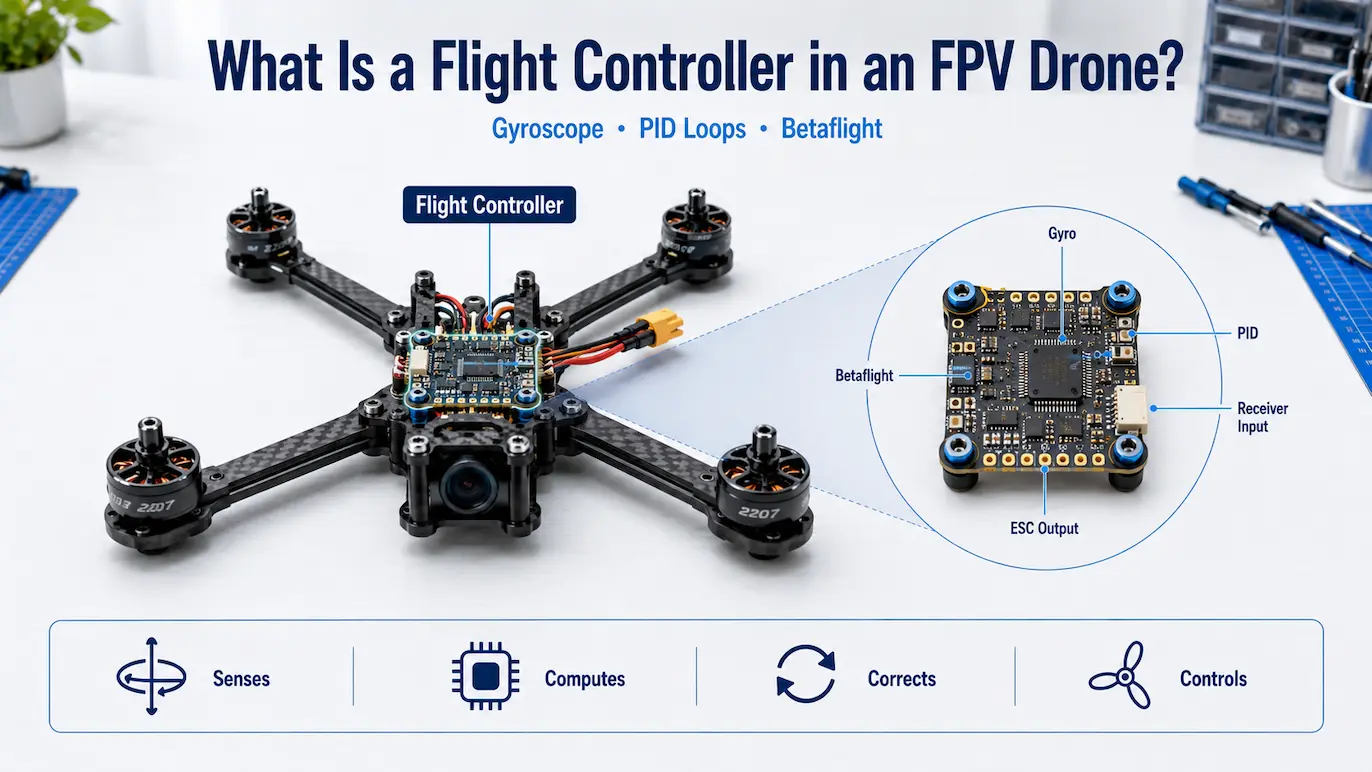
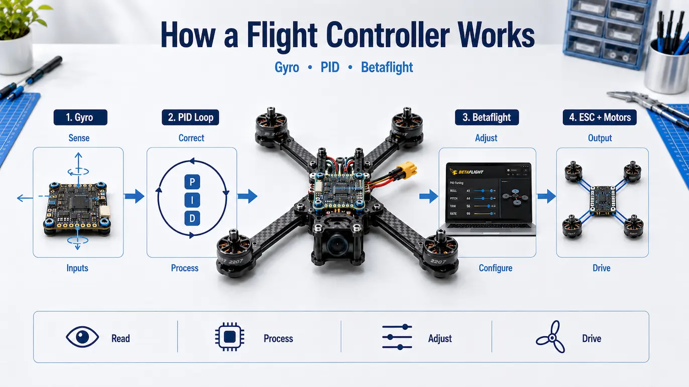
FPV flight controller explained in practical terms: it is the processing board that reads gyroscope data, interprets pilot commands, calculates PID corrections, mixes motor outputs, and sends separate instructions to each electronic speed controller.
The flight controller does not supply high-current power to the motors. It determines how each motor should respond, while the ESC controls the electrical power delivered to that motor.
During flight, the board continuously:
- Receives commands from the radio receiver.
- Reads rotational movement from the gyroscope.
- Compares requested movement with measured movement.
- Calculates corrective output.
- Distributes corrections across the motors.
- Sends updated commands to the ESC channels.
- Measures the aircraft’s response.
- Repeats the process.
Betaflight is flight-control firmware commonly used to perform these functions on FPV multirotors. Understanding this control path makes it easier to evaluate gyroscopes, PID loops, motor mixing, ESC communication, board features, mounting requirements, and compatibility.
Table of Contents
- FPV Flight Controller Explained: How It Works
- The Flight Controller’s Role in the Drone Industry
- Where the Flight Controller Fits
- Main Flight Controller Components
- Gyroscope and Accelerometer Functions
- Gyro Sampling and Mechanical Vibration
- PID Loop Basics
- Higher Gains and Oscillation
- Fast Forward and Full Throttle Flight
- Motor Mixing and ESC Communication
- Betaflight Firmware and Configurator
- Ports, Orientation, and Mounting
- Flight Controller and ESC Compatibility
- How to Choose a Flight Controller
- Final Verdict
FPV Flight Controller Explained: How It Works
The flight controller coordinates the aircraft’s control system. It acts as the decision-making layer between pilot input, onboard sensors, firmware, ESC channels, and motors.
Its primary responsibilities include:
- reading motion sensors;
- receiving commands from the radio receiver;
- calculating stabilization corrections;
- determining the output required from each motor;
- sending commands to the ESC;
- running flight-control firmware;
- communicating with supported peripherals.
A quadcopter cannot be controlled by sending the same output to all four motors.
Each motor must be adjusted independently to create or resist movement around the roll, pitch, and yaw axes.
When a pilot requests a roll to the right, the controller changes the relative output of motors on opposite sides of the frame. When the aircraft rotates faster or slower than requested, the controller detects the difference and updates the motor commands.
This repeated measurement-and-correction process is the foundation of stable multirotor control.
The Flight Controller’s Role in the Drone Industry
Across the drone industry, flight controllers connect radio input, onboard sensors, motor-control hardware, and flight-control software.
FPV systems usually prioritize:
- low-latency manual control;
- rapid rotational response;
- compact electronics;
- configurable firmware;
- compatibility with racing and freestyle hardware.
Other drone categories may prioritize assisted navigation, position holding, mapping, or automated missions. Those aircraft still require a controller that interprets sensor data and coordinates motor output, but their firmware and sensor requirements may differ.
This article remains focused on flight controllers used in FPV multirotors rather than complete autonomous-drone systems.
Where the Flight Controller Fits in the FPV System
A simplified control path is:
Radio transmitter → receiver → flight controller → ESC → motors
The receiver takes pilot commands transmitted over the radio link and passes them to the flight controller.
The flight controller combines those commands with sensor measurements and generates an individual output for each ESC channel.
The ESC then controls the high-current electrical output supplied to its motor.
The FPV video path is separate:
FPV camera → video transmitter → receiver or goggles
A flight controller may provide power, configuration access, voltage information, or on-screen data for supported video hardware. It does not replace the camera, video transmitter, receiver, or goggles.
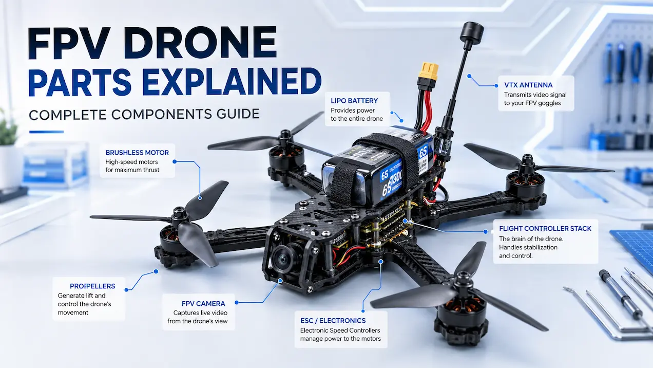
The broader FPV parts guide explains how the major components connect across the complete aircraft.
Main Parts of an FPV Flight Controller
Flight-controller boards differ in dimensions, processor family, connector layout, and onboard features. Most boards still contain several core hardware sections.
Microcontroller
The microcontroller runs the flight-control firmware and performs the calculations required to process sensor data and generate motor output.
Its tasks may include:
- reading gyro measurements;
- processing receiver commands;
- calculating control corrections;
- mixing motor outputs;
- managing configured peripherals;
- monitoring supported safety conditions.
The microcontroller must complete these tasks with consistent timing.
A faster processor can provide more computing capacity, but processor generation alone does not determine flight quality.
Gyro implementation, firmware support, PCB design, mechanical vibration, mounting, and configuration also affect the final behavior.
Gyroscope
The gyroscope measures angular velocity around the pitch and roll axes and around the vertical yaw axis.
The three rotational axes are:
- Roll: rotation around the front-to-back axis.
- Pitch: rotation around the side-to-side axis.
- Yaw: rotation around the vertical axis.
The gyro does not measure geographic position. It reports how quickly the aircraft is rotating.
The flight controller compares this measured rotation with the movement requested by the pilot.
Accelerometer
Many FPV flight controllers also include an accelerometer.
The accelerometer measures acceleration along three axes. Gravity provides a reference that firmware can use when estimating which direction is level.
| Sensor | Primary measurement | Typical control role |
|---|---|---|
| Gyroscope | Angular velocity | Rate control and rotational correction |
| Accelerometer | Linear acceleration, including gravity | Level-reference support |
In Acro mode, normal rate control primarily uses gyro feedback rather than an accelerometer-based level target.
Self-leveling modes use accelerometer information in addition to gyro data. Detailed differences between Acro, Angle, and Horizon belong to the dedicated flight-modes article.
Different Features on Flight Controller Boards
Depending on the model, additional onboard hardware may include:
- a barometer;
- flash memory for Blackbox logging;
- an SD-card slot;
- current-sensor input;
- voltage-sensor input;
- regulated power outputs;
- serial communication ports;
- GPS connectivity;
- an analog on-screen-display circuit.
These components do not all perform stabilization.
They may support:
- flight-data recording;
- voltage monitoring;
- current monitoring;
- peripheral communication;
- regulated power delivery;
- on-screen telemetry.
GPS connectivity does not mean the board automatically provides autonomous navigation or obstacle avoidance. Available GPS functions depend on the firmware, receiver quality, configuration, and supporting hardware.
Select a board according to the functions required by the aircraft rather than the total number of advertised features.
How the Gyroscope Measures Movement
The gyro produces separate rotational-rate measurements for roll, pitch, and yaw.
Suppose the pilot requests a roll rate to the right. The controller compares that setpoint with the roll rate reported by the gyro.
The aircraft may be:
- rotating at the requested rate;
- rotating too slowly;
- rotating too quickly;
- rotating in the wrong direction.
The difference between requested and measured movement is the control error.
The flight controller calculates a correction, updates the relative motor outputs, and then reads the next gyro measurement to determine how the aircraft responded.
This cycle runs continuously during flight.
What Is Gyro Sampling Rate?
Gyro sampling rate describes how frequently the sensor generates new rotational measurements.
A higher numerical rate can provide more frequent data, but it does not automatically produce better flight performance.
Useful sensor processing also depends on:
- the gyro model;
- sensor-to-processor communication;
- firmware support;
- processor workload;
- control-loop timing;
- filtering;
- electrical noise;
- mechanical vibration.
The controller must process the measurements with stable and consistent timing.
A high sampling rate offers limited benefit when the hardware or firmware cannot maintain reliable processing.
Gyro Data and Mechanical Vibration
The gyroscope detects actual aircraft movement, but it can also detect unwanted mechanical vibration.
Possible vibration sources include:
- damaged motors;
- bent motor shafts;
- worn bearings;
- damaged propellers;
- loose frame hardware;
- flexible frame sections;
- poorly supported electronics;
- wires pressing against the board.
Firmware filtering can reduce the influence of unwanted signal content. It cannot fully compensate for a severe mechanical defect.
Detailed filter configuration, Blackbox diagnosis, and vibration troubleshooting belong to dedicated tuning content.
The important point is that stable control depends on clean and trustworthy gyro data.
What Is a PID Loop?
A PID loop is a feedback-control method used to reduce the difference between requested movement and measured movement.
PID represents three terms:
- P — Proportional
- I — Integral
- D — Derivative
The controller calculates these terms from the control error and combines their output into a correction.
PID control helps the aircraft follow requested rotational movement, resist disturbances, and limit overshoot.
This article explains the functions of the terms. It does not provide values, presets, or step-by-step tuning procedures.
The official Betaflight PID guide provides dedicated documentation for pilots who need tuning information.
What Does the Proportional Term Do?
The proportional term responds to the current control error.
When the difference between requested and measured movement is large, the proportional response becomes larger. When the difference is small, the response becomes smaller.
In simplified terms:
- small present error produces a smaller correction;
- large present error produces a larger correction.
A stronger proportional response makes the controller react more aggressively to present error.
If the response becomes excessive, the aircraft can overshoot and repeatedly correct around the requested rate.
What Does the Integral Term Do?
The integral term responds to error that continues over time.
Persistent influences may include:
- uneven weight distribution;
- sustained airflow;
- prolonged maneuvering load;
- continuing rotational bias.
The integral term accumulates continuing error and adds a correction intended to maintain the requested behavior.
Its primary role is long-term authority against persistent disturbances.
Detailed windup behavior and I-gain adjustment belong to dedicated PID-tuning content.
What Does the Derivative Term Do?
The derivative term responds to how quickly the control error is changing.
Its main role is damping. It can reduce overshoot when the aircraft approaches or moves beyond the requested rate too quickly.
A simplified distinction is:
- P responds to present error.
- I responds to accumulated error.
- D responds to changing error.
Derivative response is sensitive to rapid changes in gyro data. This is why mechanical vibration and filtering quality affect how reliably the D term can provide damping.
Excessive derivative response can also amplify noise and contribute to motor heating.
Higher Gains and Control Response
Higher gains make the control loop respond more strongly, but each term changes a different part of the response.
A higher P value increases correction strength for present error.
A higher I value increases authority against continuing error.
A higher D value increases damping against rapid changes.
Higher values are not automatically better. Excessive gain can cause the system to:
- overreact;
- amplify gyro noise;
- produce oscillation;
- increase motor temperature;
- create mechanical or electrical stress.
Suitable values depend on the aircraft’s frame, motors, propellers, mass, vibration level, and firmware configuration.
Slow Oscillation
A slow oscillation is a repeated low-frequency movement in which the aircraft rocks, wanders, or corrects back and forth.
It differs from a rapid, high-frequency vibration.
Possible causes can include:
- control settings;
- uneven weight distribution;
- mechanical flexibility;
- sustained external forces;
- propulsion inconsistencies.
Slow oscillation is a symptom rather than one universal fault. It should not be diagnosed from appearance alone.
Detailed oscillation diagnosis belongs to dedicated troubleshooting and PID-tuning content.
How the PID Terms Work Together
During rapid stick movements, sharp turns, or other rotational commands, the feedback sequence remains the same:
- The pilot requests a rotational rate.
- The gyro measures the actual rate.
- The controller calculates the difference.
- P responds to present error.
- I responds to continuing error.
- D contributes damping.
- The controller combines the terms.
- The motor mixer distributes the correction.
- Updated commands are sent to the ESC.
- The gyro measures the resulting movement.
The controller applies feedback calculations to the roll, pitch, and yaw axes.
A yaw PID loop follows the same setpoint-versus-gyro principle, although a quadcopter creates yaw torque differently from pitch and roll torque.
The physical response also depends on the frame, motors, propellers, mass, and power system. Detailed propulsion matching belongs to the FPV motor guide rather than this flight-controller article.
Setpoint vs Gyro Measurement
The setpoint represents the movement requested by the pilot’s stick movements or another active control function.
In rate-based flight, the setpoint commonly represents a requested rotational rate around the roll, pitch, or yaw axis.
The gyro measurement represents the rotation the aircraft is actually producing.
The basic relationship is:
Control error = requested movement − measured movement
When measured movement follows the setpoint closely, the error is small.
When the aircraft does not follow the request, the error increases.
The PID controller uses this difference to calculate corrective output.
This setpoint-versus-measurement relationship is the foundation of closed-loop flight control.
Fast Forward Flight
During fast forward flight, the aircraft uses the same feedback-control process that applies at lower speed.
The pilot’s stick movements create rotational setpoints. The gyro measures the actual response, and the PID loop corrects the difference.
The flight controller does not switch to a separate control method because the aircraft is moving faster.
However, aerodynamic load, vibration, and available motor authority may change as speed and maneuver intensity increase.
Specific tests performed during fast forward flight belong to a dedicated tuning article.
Full Throttle Behavior
At full throttle, the motors have less unused output range available for additional corrective commands.
The controller continues calculating roll, pitch, and yaw corrections. However, the final motor output cannot exceed the available range of the propulsion system.
This can reduce remaining control authority during aggressive acceleration or high-load maneuvers.
Detailed motor saturation, throttle management, anti-gravity behavior, and related tuning belong to advanced content.
How Motor Mixing Works
After calculating throttle, roll, pitch, and yaw requirements, the flight controller converts those requirements into individual commands for each motor.
This process is called motor mixing.
The four motors normally receive different commands during a maneuver.
For example:
- roll changes the relative output between the left and right sides;
- pitch changes the relative output between the front and rear;
- yaw changes the balance between opposite motor-rotation directions;
- throttle raises or lowers the base output across all motors.
The mixer combines:
- throttle demand;
- roll correction;
- pitch correction;
- yaw correction.
The final command for each motor is sent to its corresponding ESC channel.
This article covers standard quadcopter mixing. Custom motor mixers and non-quad configurations require separate treatment.
How the Flight Controller Communicates With the ESC
The flight controller generates an individual command for each ESC channel.
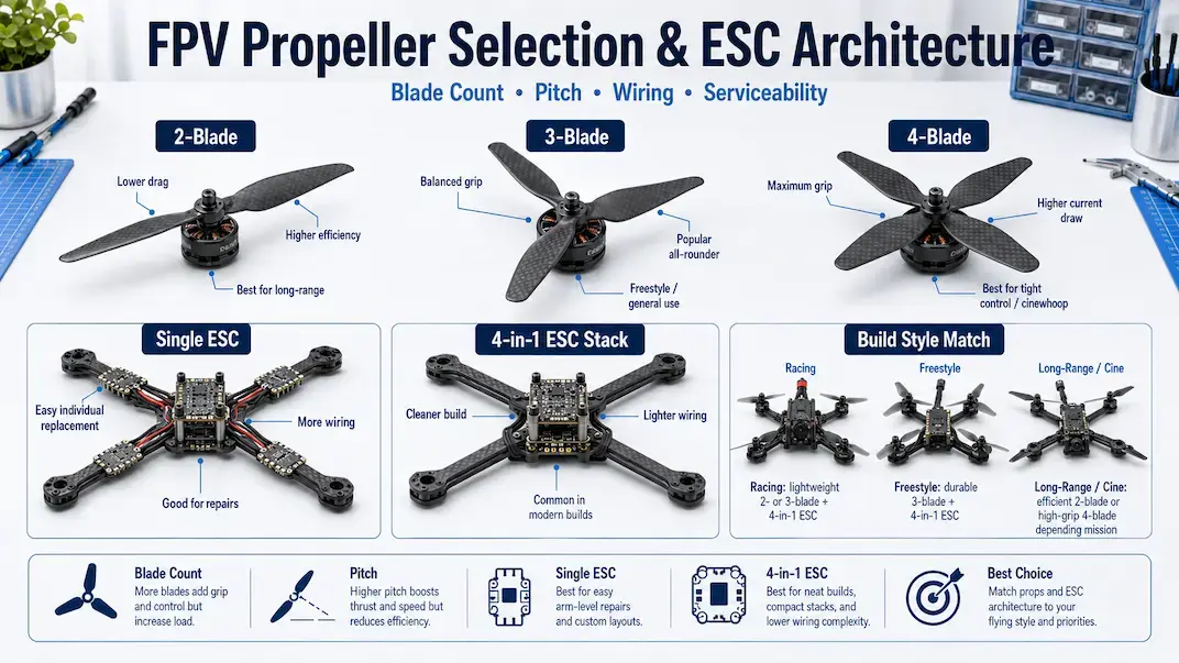
With four individual ESCs, the commands commonly travel through separately routed signal wires.
With a 4-in-1 ESC, the signals normally travel through a short harness or grouped solder connections.
The previous guide to ESC architecture compares these layouts by wiring, placement, weight, heat distribution, and repair scope.
The flight controller generates the motor commands.
The ESC performs the high-current electrical switching required to drive the motor.
The flight controller does not send battery power directly to the motor.
Motor-Output Communication
A motor-output protocol defines how the flight controller communicates requested output to the ESC.
Compatibility depends on:
- flight-controller firmware;
- ESC firmware;
- wiring;
- configured output method;
- supported hardware.
The protocol with the highest numerical rate is not automatically the best option.
Correct wiring, stable communication, and reliable firmware support matter more than choosing the largest available number.
Detailed protocol comparison, bidirectional communication, ESC telemetry, and ESC firmware belong to future ESC-configuration content.
What Is Betaflight?
Betaflight is flight-control firmware used on many FPV drone flight controllers.
It manages functions such as:
- sensor processing;
- receiver input;
- PID calculations;
- motor mixing;
- motor-command output;
- configured flight behavior;
- peripheral communication;
- safety logic.
The physical board provides the processor, sensors, memory, solder pads, connectors, and power circuits.
Betaflight provides the software that coordinates those resources.
Two boards running Betaflight can still behave differently because of differences in:
- gyro implementation;
- processor capacity;
- PCB design;
- firmware target;
- connected hardware;
- aircraft mechanics;
- configuration.
Betaflight Firmware vs Betaflight Configurator
Betaflight firmware runs on the flight-controller board.
The official Betaflight App provides the interface used to view and change supported firmware settings.
The application may provide access to:
- ports;
- receiver configuration;
- motor output;
- sensor alignment;
- flight modes;
- PID gains;
- filters;
- on-screen display;
- connected peripherals.
This article does not provide a complete Betaflight installation or configuration tutorial.
Each configuration area has its own search intent and should be covered separately.
In-Depth Flight Processing Sequence
At a simplified level, Betaflight repeatedly:
- Reads the gyro.
- Processes sensor measurements.
- Reads the current setpoint.
- Calculates control error.
- Runs PID calculations.
- Mixes corrections across the motors.
- Updates motor output.
- Repeats the cycle.
Receiver processing, safety checks, peripheral communication, and other configured tasks run alongside this control loop.
The exact timing depends on:
- flight-controller hardware;
- firmware version;
- sensor configuration;
- enabled features.
The important point is that control is continuous. The board repeatedly measures the aircraft’s response and updates its output.
Flight Controller Ports and Connections
Common flight-controller connections include:
- motor outputs;
- ESC interface;
- receiver input;
- USB;
- serial communication ports;
- buzzer output;
- LED output;
- voltage-sensor input;
- current-sensor input;
- supported video-system connections.
Serial communication ports are commonly identified as UARTs.
A UART can provide an independent communication path for a compatible device.
The number of available UARTs can affect how many serial peripherals the board can support simultaneously.
Not every component requires a UART. Some use dedicated pads, USB, sensor buses, or other interfaces.
Flight Controller Orientation
The firmware must know how the board is positioned relative to the aircraft.
A board installed in its intended forward direction may use the default alignment.
A rotated or flipped board requires the corresponding orientation setting.
Incorrect alignment can cause movement to be interpreted on the wrong axis or in the wrong direction.
For example, physical pitch movement could be interpreted as roll if the configured orientation does not match the installation.
Orientation is a basic installation requirement, not a PID adjustment.
Flight Controller Mounting
The flight controller must be secured while limiting unnecessary vibration transfer to the gyro.
Many boards use rubber grommets or other soft-mounting hardware.
The purpose is not to let the board move freely. It is to reduce high-frequency vibration while maintaining a stable installation.
Potential mounting problems include:
- excessively compressed grommets;
- loose stack hardware;
- wires pulling against the board;
- metal hardware touching components;
- damaged isolation material;
- inadequate clearance between boards.
Mechanical installation can affect gyro measurements even when firmware settings remain unchanged.
Flight Controller Processor Families
Flight controllers are often identified by their microcontroller family.
The processor can affect:
- computing capacity;
- memory;
- peripheral support;
- firmware compatibility;
- available board functions.
A faster processor does not automatically produce better flight behavior.
The complete board should also be evaluated according to:
- supported firmware target;
- gyro implementation;
- port availability;
- power regulation;
- onboard storage;
- connector layout;
- documentation;
- mounting dimensions.
The correct board is the one that supports the required aircraft without creating unnecessary compatibility or installation problems.
Flight Controller and ESC Compatibility
A flight controller and ESC must be physically and electrically compatible.
Important checks include:
- mounting pattern;
- connector pinout;
- motor-signal connections;
- ground connections;
- battery-voltage sensing;
- current-sensor output;
- telemetry support;
- regulated-voltage connections.
A connector that fits physically may still use a different pin arrangement.
Compare the wiring diagrams for both boards before connecting a flight controller to a 4-in-1 ESC.
Incorrect wiring can place battery voltage on a signal or regulated-voltage pin.
Builders reviewing integrated hardware can use the flight controller ESC category after identifying the required mounting and electrical specifications.
What a Flight Controller Does Not Do
A flight controller does not:
- supply high-current motor power;
- replace the ESC;
- transmit the pilot’s radio signal;
- generate the FPV camera image;
- transmit the video link;
- determine frame strength;
- replace correct motor selection;
- eliminate severe mechanical vibration through software;
- provide obstacle avoidance by itself.
Obstacle avoidance requires suitable sensors, compatible processing, firmware support, and navigation logic.
It is not a standard core function of a typical Betaflight flight controller.
Common Flight Controller Misconceptions
The Flight Controller Powers the Motors
The flight controller generates commands. The ESC controls the high-current electrical output supplied to the motors.
The Gyroscope Measures Position
The gyro measures rotational rate. It does not provide geographic position.
A Higher Sampling Rate Is Always Better
Higher sensor rates do not guarantee cleaner data or better control. Processing timing, firmware support, filtering, and vibration also matter.
PID Is a Flight Mode
PID is part of the feedback-control system. Flight modes determine how pilot input and sensor information are interpreted.
Betaflight Is the Physical Board
Betaflight is firmware. The flight controller is the hardware that runs it.
A Faster Processor Fixes Mechanical Problems
More processing capacity cannot repair a damaged motor, loose frame, bent shaft, damaged propeller, or severe vibration source.
Matching Connectors Are Automatically Compatible
Matching connector shapes do not guarantee matching electrical pinouts.
Wi-Fi Is Required for Flight Control
Wi-Fi is not part of the normal real-time path between the receiver, flight controller, ESC, and motors.
Some boards or external modules may provide wireless configuration. That is a secondary feature rather than a core flight-control requirement.
How to Choose an FPV Flight Controller
A suitable board must match the aircraft’s physical, electrical, and functional requirements.
Mounting Pattern
Confirm that the mounting-hole spacing fits the frame’s electronics bay.
ESC Interface
Check:
- motor outputs;
- connector pinout;
- voltage sensing;
- current sensing;
- telemetry;
- regulated power;
- ground connections.
Available Ports
Count the communication ports required for the receiver and planned peripherals.
Firmware Support
Confirm that the board has a supported firmware target and adequate documentation.
Sensor Implementation
Verify that the onboard gyro is supported by the intended firmware.
Board Orientation
Ensure the USB port, connectors, and solder pads remain accessible after installation.
Power Requirements
Check the supported input voltage and the voltage and current limits of onboard regulators.
Physical Clearance
Confirm:
- stack height;
- board dimensions;
- USB access;
- wire routing;
- clearance from adjacent hardware.
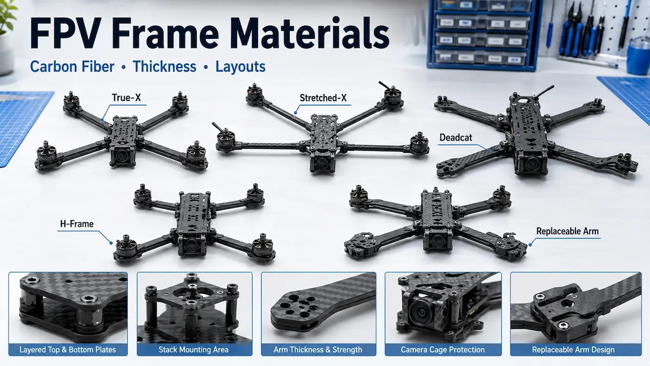
The next guide will explain how to choose FPV frames according to mounting dimensions, electronics space, arm design, motor-hole pattern, and intended configuration.
Those frame-selection decisions are not repeated here.
Flight Controller Processing Summary
| Stage | Flight-controller action |
|---|---|
| 1 | Receive pilot input |
| 2 | Read gyro measurements |
| 3 | Determine requested movement |
| 4 | Compare requested and measured rotation |
| 5 | Calculate PID correction |
| 6 | Mix corrections across the motors |
| 7 | Send commands to the ESC channels |
| 8 | Measure the aircraft’s response |
| 9 | Repeat continuously |
Final Verdict
FPV flight controller explained simply: it is the processing center that connects pilot commands, gyroscope feedback, PID calculations, motor mixing, and ESC output.
It:
- receives pilot input;
- measures rotational movement;
- compares requested and measured behavior;
- calculates PID corrections;
- mixes those corrections across the motors;
- sends separate commands to the ESC channels;
- runs the flight-control firmware.
The gyro reports how quickly the aircraft is rotating.
The PID loop calculates the required corrective response.
Betaflight provides the firmware environment that performs these functions on compatible hardware.
A flight controller should be selected according to:
- mounting pattern;
- firmware support;
- gyro implementation;
- available ports;
- ESC compatibility;
- power requirements;
- physical installation.
Processor branding alone should not determine the selection.
Additional FPV technical guides cover connected systems within their own separate search intents.